Software Renderer in Odin from Scratch, Part V
30th July 2025 • 20 min read
We've already covered a lot in the previous four parts without much of a visual feedback. In this part, we're finally going to see some interesting results, as we'll implement draw.odin to finish our pipeline, which will be capable of rendering our mesh in two modes: wireframe without and with backface culling.
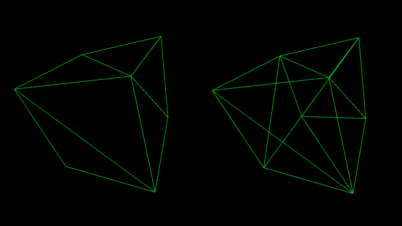
As you can see in the image above, backface culling means skipping the rendering of faces that point away from the camera. We briefly mentioned this in the previous part, but in this part, we're going to understand how this optimization technique works.
It's not often used in wireframe mode, since being able to see "through" the model is usually desirable. However, since we're implementing our own software renderer from scratch, it's up to us how we do it, and I find it useful, for demonstration purposes, to support backface culling in wireframe mode as well. There will be a dedicated part of this series just for optimization, but backface culling is so essential that I decided to include it from the beginning.
Once we rasterize our faces, or our triangles, if you wish, they'll appear solid; that's what rasterization is about in a nutshell. In that case, not having backface culling enabled doesn’t make sense, since we can't see through a solid object anyway. Therefore, in the rasterized modes we'll implement in subsequent parts, backface culling will always be enabled.
I previously mentioned the camera, which is a concept we talked about when discussing transformations and different spaces, especially the view space. In this part, we're also going to implement camera.odin. We're also going to implement inputs.odin to move, rotate, and scale our mesh at runtime. At the end of this part, you'll be able to see something like this:
In the previous parts, there was always a theory first, followed by the implementation in Odin. In this part, we're going to switch to a slightly different style, where I'll explain the theory alongside the implementation.
Implementing camera.odin
Let's start with the simplest one, camera.odin, where we define the Camera struct and a factory method for instantiating it. Our camera will consist of two vectors: the position of the camera itself and the position of the target. You know that when we subtract vector B from vector A, the resulting vector is the direction from A to B. This is how we, for example, calculate the forward vector in our MakeViewMatrix procedure, which we previously implemented in matrix.odin, and we covered the concept in Part II:
forward := Vector3Normalize(eye - target)
Soon, we pass the position of a camera as eye and also its target to the MakeViewMatrix procedure, but now, add a new file named camera.odin, and after the usual package definition, define the Camera struct and a factory method that accepts the position and target for the new camera:
package main

Camera :: struct {
    position: Vector3,
    target: Vector3
}

MakeCamera :: proc(position, target: Vector3) -> Camera {
    camera: Camera
    camera.position = position
    camera.target = target
    return camera
}
Implementing inputs.odin
Before we dive back into rendering, let's first implement the input handling. Create a new file called inputs.odin. It will contain just a single procedure that accepts translation, rotation, and scale, as well as the render mode index as mutable references. It will also take the count of render modes, so we can cycle through them using left and right arrow keys, and the delta time to keep our logic frame-time independent.
We'll return to the concept of delta time soon. Now, let's proceed with the implementation.
package main

import rl "vendor:raylib"

HandleInputs :: proc(translation, rotation: ^Vector3, scale: ^f32, renderMode: ^i8, renderModesCount: i8, deltaTime: f32) {
Passing by a pointer (using ^ in front of a type, e.g., ^Vector3) means the value can be modified inside the procedure. Once the execution flow exits the procedure, the original variable remains modified because we accessed it via its address rather than copying its value into a new variable that's valid only in the scope of a procedure.
You probably already know the difference between passing by reference and passing by value, especially if you're coming from C or C++, where you distinguish between passing by pointer, by reference, or by value, and whether each is mutable or immutable. I just wanted to briefly mention this because in Odin, it works a bit differently and, in my opinion, much more user-friendly.
In Odin, you don’t need to think about it as much as in C or C++. You only pass by pointer if you want the value to be mutable inside the procedure and that's it. Otherwise, you don't need to worry about it at all; the compiler decides whether to copy it or pass it as an immutable reference, which it will when the value is larger than the size of a pointer (8 bytes on 64-bit machines). Isn't Odin a great language?
Let's proceed with the implementation of the HandleInputs procedure. We need variables for linear and angular step sizes, one for translation and scaling, the other for rotation. But it would be nice to slow things down when holding Left Shift, so we'll define these values using a ternary operator like this.
linearStep: f32 = (rl.IsKeyDown(rl.KeyboardKey.LEFT_SHIFT) ? 0.25 : 1) * deltaTime
angularStep: f32 = (rl.IsKeyDown(rl.KeyboardKey.LEFT_SHIFT) ? 12 : 48) * deltaTime
Notice how we multiply these values by the aforementioned deltaTime. The HandleInputs procedure will be called in main.odin every frame, that is, inside the main loop, which keeps running while rl.WindowShouldClose() returns false.
The deltaTime represents the time that passes during a single frame, and raylib provides a built-in procedure for getting it, GetFrameTime(). This makes things a bit easier for us; we don’t need to calculate it manually, though doing so is relatively easy, and you can find many implementations online.
The key idea here is that a faster computer would iterate over our main loop more quickly than a slower one, and even on the same machine, frame time can vary depending on how much work is being done during that frame. Without scaling our steps by deltaTime, the mesh would translate, scale, and rotate faster at higher frame rates, and slower at lower ones.
That said, just scaling deltaTimealone isn’t a perfect solution. It's a good approximation for most use cases, but small variations between frames or large spikes in frame time can still lead to inconsistent motion or jitter. For very precise or deterministic simulations, like physics simulations, more advanced time-stepping techniques may be necessary.
If you're interested in this topic, I do recommend the Tools of the Trade talk by Ginger Bill, creator of the Odin language, from Better Software Conference 2025, but now, back to our procedure.
if rl.IsKeyDown(rl.KeyboardKey.W) do translation.z += linearStep
if rl.IsKeyDown(rl.KeyboardKey.S) do translation.z -= linearStep
if rl.IsKeyDown(rl.KeyboardKey.A) do translation.x += linearStep
if rl.IsKeyDown(rl.KeyboardKey.D) do translation.x -= linearStep
if rl.IsKeyDown(rl.KeyboardKey.E) do translation.y += linearStep
if rl.IsKeyDown(rl.KeyboardKey.Q) do translation.y -= linearStep

if rl.IsKeyDown(rl.KeyboardKey.J) do rotation.x -= angularStep
if rl.IsKeyDown(rl.KeyboardKey.L) do rotation.x += angularStep
if rl.IsKeyDown(rl.KeyboardKey.O) do rotation.y += angularStep
if rl.IsKeyDown(rl.KeyboardKey.U) do rotation.y -= angularStep
if rl.IsKeyDown(rl.KeyboardKey.I) do rotation.z += angularStep
if rl.IsKeyDown(rl.KeyboardKey.K) do rotation.z -= angularStep

if rl.IsKeyDown(rl.KeyboardKey.KP_ADD) do scale^ += linearStep
if rl.IsKeyDown(rl.KeyboardKey.KP_SUBTRACT) do scale^ -= linearStep
Nothing complicated is happening here; we simply increment or decrement the components of our translation vector when the W, S, A, D, E, or Q keys are pressed, modify rotation similarly using the J, L, O, U, I, and K keys. And the plus and minus keys are used to increase or decrease the scale value. Notice the usage of the do keyword, instead of { }. I personally find Odin's do nice for one-liners like these.
The last thing we need to do is increment or decrement renderMode when the left or right arrow key is pressed. We also want the value to wrap around. That means, with 8 render modes (which we’ll have by the end of this series), if the current renderMode is 0 and we press the left arrow key, it should wrap to 8. Likewise, if the renderMode is 8 and we press the right arrow key, it should wrap back to 0. And this is a job for the modulo operator (%)!
if rl.IsKeyPressed(rl.KeyboardKey.LEFT) {
        renderMode^ = (renderMode^ + renderModesCount - 1) % renderModesCount
    } else if rl.IsKeyPressed(rl.KeyboardKey.RIGHT) {
        renderMode^ = (renderMode^ + 1) % renderModesCount
    }
}
Implementing draw.odin
Now, let's create a new file, name it draw.odin. From this point, until the very end of the series, this will be the file we'll put in the most effort. First, we add a package definition and import raylib and math.
package main

import rl "vendor:raylib"
import "core:math"
Then we'll proceed with implementing the DrawWireframe procedure. This procedure accepts transformed vertices, triangles, and a projection matrix, a perspective projection matrix in our case, though later, we'll also implement switching between orthographic and perspective projections. The procedure also accepts a color to draw mesh lines with and a flag we'll use to switch between two modes: with backface culling enabled and disabled.
DrawWireframe :: proc(
    vertices: []Vector3,
    triangles: []Triangle,
    projMat: Matrix4x4,
    color: rl.Color,
    cullBackFace: bool
) {
In the body of this procedure, we'll iterate over all triangles and pull out the vertices that the current triangle is made of.
for &tri in triangles {
    v1 := vertices[tri[0]]
    v2 := vertices[tri[1]]
    v3 := vertices[tri[2]]
Then we check if cullBackFace is set to true, and if so, we find out whether the face is indeed facing away using the IsBackFace procedure, which we yet need to implement. In case the procedure returns true, we skip rendering of this triangle and continue to the next one.
if cullBackFace && IsBackFace(v1, v2, v3) {
    continue
}
Otherwise, we find the screen positions of each vertex using ProjectToScreen, another crucial procedure we’re going to implement soon.
p1 := ProjectToScreen(projMat, v1)
p2 := ProjectToScreen(projMat, v2)
p3 := ProjectToScreen(projMat, v3)
Now that we have the screen positions, there's one more optimization I'd like to implement, and that is skipping triangles that have at least one vertex outside the frustum.
We discussed the frustum in Part III, where we covered transformations. Just a brief reminder, it's the volume bounded by the near, far, top, bottom, left, and right planes, and it defines our visible area. While the position of near and far planes is optional, the others are typically determined by our screen dimensions.
if (IsFaceOutsideFrustum(p1, p2, p3)) {
    continue
}
And to complete our DrawWireframe procedure, we call the DrawLine procedure, which we also need to implement, three times to draw lines in the screen space from p1 to p2, then from p2 to p3, and from p3 back to p1, essentially drawing a single triangle.
DrawLine(p1.xy, p2.xy, color)
DrawLine(p2.xy, p3.xy, color)
DrawLine(p3.xy, p1.xy, color)
}
}
We're using a neat feature of Odin. We have an array of three elements. We previously defined an alias Vector3 for it in vectors.odin, but under the hood, p1, p2, and p3 are of type [3]f32. However, theDrawLine will accept parameters of Vector2, which is our alias for [2]f32, so we're passing p1.xy, p2.xy, and p3.xy, converting Vector3 to Vector2 using just the first two elements.
Odin actually offers more tricks like this one. You can read about them in the Array Programming section in its documentation. I highly recommend that you do so. But now, let's proceed by implementing the IsBackFace procedure.
IsBackFace :: proc(v1, v2, v3: Vector3) -> bool {
    edge1 := v2 - v1
    edge2 := v3 - v1

    cross := Vector3CrossProduct(edge1, edge2)
    crossNorm := Vector3Normalize(cross)
    toCamera := Vector3Normalize(v1)

    return Vector3DotProduct(crossNorm, toCamera) >= 0.0
}
You might be wondering how this works if we don't pass in the camera. The reason is that these vertices are already transformed into view space (sometimes referred to as camera space), and in view space, the camera is always positioned at the origin [0,0,0].
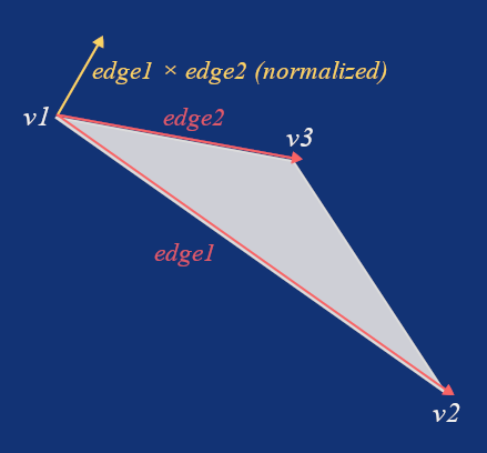
So, if we get two vectors pointing from v1 in the directions of v2 and v3, which we called edge1 and edge2, and then compute their cross product and normalize it, we get a unit vector pointing perpendicularly to the triangle. We called this vector cross, but it's also known as the normal. We talked about normals in the previous part.
Now, if we calculate the dot product between the normalized v1 and the normal, we can be sure the triangle is facing away from the camera if this dot product is greater than 0.
We implemented Vector3CrossProduct, Vector3Normalize, and Vector3DotProduct in vectors.odin after we covered the math topics fundamental to this project. If you need a refresher, take another look at that in Part II.
Let's now implement the ProjectToScreen procedure, which is one of the most important procedures in our rendering pipeline, so I'll go over it step by step. We saw that our procedure needs a projection matrix and a point transformed into view space.
ProjectToScreen :: proc(mat: Matrix4x4, p: Vector3) -> Vector3 {
Inside the procedure, we first use the projection matrix to transform the point p into clip space, but we're also adding the fourth component w, set to 1. You'll see why we're doing that in a moment.
clip := Mat4MulVec4(mat, Vector4{p.x, p.y, p.z, 1.0})
Now that we've transformed the point to clip space, we use the inverse of the w component to perform perspective division, effectively getting X and Y in Normalized Device Coordinates (NDC) in the range of -1 to 1.
invW : f32 = 1.0 / clip.w

ndcX := clip.x * invW
ndcY := clip.y * invW
However, we set the screen resolution to 800×600 pixels in constants.odin, so to get the actual screen position, we need to shift the coordinates from the range of -1 to 1 to the range of 0 to 1 and then, we multiply them by the screen width and screen height, respectively, while we also flip the Y, since the origin of our screen is at the top-left, not the bottom-left.
screenX := ( ndcX * 0.5 + 0.5) * SCREEN_WIDTH
screenY := (-ndcY * 0.5 + 0.5) * SCREEN_HEIGHT
And that’s it, now we simply return the point in screen space, but we also carry outinvW as the z component.
return Vector3{screenX, screenY, invW}
}
Before actually drawing lines between points, we need to check whether all points are inside the visible frustum, as we mentioned earlier. First, we check if the z components (which are now the values of invW from the ' ProjectToScreen ProjectToScreenprocedure) of all points are in the range of -1 to 1, in other words, if points are behind the near plane and in front of the far plane.
IsFaceOutsideFrustum :: proc(p1, p2, p3: Vector3) -> bool {
    if (p1.z >  1.0 || p2.z >  1.0 || p3.z >  1.0) ||
       (p1.z < -1.0 || p2.z < -1.0 || p3.z < -1.0) {
        return true
    }
If at least one point is outside these boundaries, we consider the entire face to be outside as well. This simplification is good enough for our case.
Then we do something similar for the left, right, top, and bottom planes, where the limits are 0, 800, 0, and 600, according to our screen resolution. Only this time, we find the minimum and maximum to create a bounding box around our triangle, and return true only if the entire bounding box is outside the visible screen area.
minX := math.min(p1.x, math.min(p2.x, p3.x))
maxX := math.max(p1.x, math.max(p2.x, p3.x))
minY := math.min(p1.y, math.min(p2.y, p3.y))
maxY := math.max(p1.y, math.max(p2.y, p3.y))
if maxX < 0 || minX > SCREEN_WIDTH ||
maxY < 0 || minY > SCREEN_HEIGHT {
return true
}
return false
}
All points that pass the backface culling test, if enabled, and the frustum culling, will be used to draw lines. For this, we need to implement the DrawLine procedure, which is the last procedure we're going to add in draw.odin today.
I know there's a DrawLine procedure provided by raylib, but as I mentioned in the first part, the goal of this series is to implement a software renderer from scratch and appreciate all the beauty behind it. Yes, we're using raylib to create and manage our window, handle inputs, and for a few other minor tasks, but drawing a line is essential for the rendering pipeline. That’s why we’re going to implement our own, just like we did with procedures related to vectors and matrices, which we could have also used from third-party libraries.
Given two points, a and b, we first calculate the differences between their X and Y components and determine whether the longer difference is horizontal or vertical.
DrawLine :: proc(a, b: Vector2, color: rl.Color) {
    dX := b.x - a.x
    dY := b.y - a.y

    longerDelta := math.abs(dX) >= math.abs(dY) ? math.abs(dX) : math.abs(dY)
We use this value to calculate the per-step increments along both axes.
incX := dX / longerDelta
incY := dY / longerDelta
Then we start drawing pixels at the position of point a, adding these increments along the x and y axes until our index reaches the longerDelta value, effectively connecting points a and b with a straight line.
x := a.x
y := a.y
for i := 0; i <= int(longerDelta); i += 1 {
rl.DrawPixel(i32(x), i32(y), color)
x += incX
y += incY
}
There's a more optimal solution than using raylib's DrawPixel like this. We can put the data into a texture, using it as a frame buffer, and then render the entire texture on the screen at the end of the frame. For that, we'll rely more on raylib, and I’m going to cover this near the end of our series, in a part dedicated entirely to optimizations.
Putting it all together in main.odin
Now that we have everything we need in the camera.odin, inputs.odin, and draw.odin, it’s time to put it all together in main.odin. Last time, we ended by creating a cube using the MakeCube procedure. Let's create our camera after that, positioned at [0, 0, -3] with the target set to [0, 0, -1] facing forward.
camera := MakeCamera({0.0, 0.0, -3.0}, {0.0, 0.0, -1.0})
Then, create two vectors, one for translation and one for rotation, and a float for scaling.
translation := Vector3{0.0, 0.0, 0.0}
rotation := Vector3{0.0, 0.0, 0.0}
scale: f32 = 1.0
We also need a count of render modes. In this part, we’ll have two of them, and another variable to hold the currently selected mode, which will always be the top one.
renderModesCount :: 2
renderMode: i8 = renderModesCount - 1
The last thing we need to do before entering our main loop is to create the projection matrix. But first, we need to go to constants.odin and add our field of view in degrees, let’s say 70 (feel free to experiment with this value), as well as our near and far plane values.
FOV :: 70
NEAR_PLANE :: 1.0
FAR_PLANE :: 100.0
Now, go back to main.odin and create the projection matrix.
projectionMatrix := MakeProjectionMatrix(FOV, SCREEN_WIDTH, SCREEN_HEIGHT, NEAR_PLANE, FAR_PLANE)
Inside our main loop, we first get the delta time, then pass it, along with renderModeCount and pointers to our other variables, into the HandleInputsprocedure.
deltaTime := rl.GetFrameTime()
HandleInputs(&translation, &rotation, &scale, &renderMode, renderModesCount, deltaTime)
Now that we can have our translation, rotation, scale, and renderMode eventually modified in HandleInputs, it’s time to create the translation, rotation, and scale matrices based on them.
translationMatrix := MakeTranslationMatrix(translation.x, translation.y, translation.z)
rotationMatrix    := MakeRotationMatrix(rotation.x, rotation.y, rotation.z)
scaleMatrix       := MakeScaleMatrix(scale, scale, scale)
Then, we use them to create our model matrix, followed by creating a view matrix and a model-view matrix by multiplying the view matrix with the model matrix. In this case, we can reuse the viewMatrix variable. This is what we covered in Part III, where we talked bout affine transformations.
modelMatrix       := Mat4Mul(translationMatrix, Mat4Mul(rotationMatrix, scaleMatrix))
viewMatrix        := MakeViewMatrix(camera.position, camera.target)
viewMatrix         = Mat4Mul(viewMatrix, modelMatrix)
Now, we use our final matrix stored as the viewMatrix to transform all the vertices. Let’s write a small procedure for that. In the previous part, we discussed the anatomy of a mesh and implemented our Mesh struct with vertices, and transformedVertices array ready to hold the vertices after transformation. We're going to use them as intended in the ApplyTransformations procedure.
ApplyTransformations :: proc(transformed: ^[]Vector3, original: []Vector3, mat: Matrix4x4) {
    for i in 0..<len(original) {
        transformed[i] = Mat4MulVec3(mat, original[i])
    }
}
And back in our main loop, we call the procedure like this.
ApplyTransformations(&mesh.transformedVertices, mesh.vertices, viewMatrix)
Finally, we can start drawing our mesh, our so far hardcoded cube, according to the selected render mode.
rl.BeginDrawing()
switch renderMode {
case 0: DrawWireframe(mesh.transformedVertices, mesh.triangles, projectionMatrix, rl.GREEN, false)
case 1: DrawWireframe(mesh.transformedVertices, mesh.triangles, projectionMatrix, rl.GREEN, true)
}
rl.EndDrawing()
rl.ClearBackground(rl.BLACK)
}
Conclusion
That's all for today. If you compile and run the project, and from now on I recommend to use optimization flag like this
odin run . -o:speed
You should see a green wireframe cube, and you should be able to switch between render modes using the arrow keys, move the cube with W, S, A, D, Q, and E keys, and rotate it using I, J, K, L, U, and O keys. If it’s not working as you've expected, you can always refer to the final code from today's part in this GitHub repository.
Enjoyed this article? Support my work ❤️
All content on this blog, which I've already put hundreds of hours into, is and always will be free.
No ads. No paywalls. No tricks.
I've personally paid for a lot of educational content, but I strongly believe knowledge should be accessible to everyone.
I also pay to keep this blog up and running, and if you like what I do here, if it has helped you, and you would like to support me, you can

Even a small contribution, the price of a coffee, is very much appreciated.
Other Parts of This Series
- Software Renderer in Odin from Scratch, Part I
- Software Renderer in Odin from Scratch, Part II
- Software Renderer in Odin from Scratch, Part III
- Software Renderer in Odin from Scratch, Part IV
- Software Renderer in Odin from Scratch, Part V
- Software Renderer in Odin from Scratch, Part VI
- Software Renderer in Odin from Scratch, Part VII
- Software Renderer in Odin from Scratch, Part VIII
- Software Renderer in Odin from Scratch, Part IX
- Software Renderer in Odin from Scratch, Part X
- Software Renderer in Odin from Scratch, Part XI
- Software Renderer in Odin from Scratch, Part XII
- Software Renderer in Odin from Scratch, Part XIII
- Software Renderer in Odin from Scratch, Part XIV


