Software Renderer in Odin from Scratch, Part VII
4th October 2025 • 7 min read
In the previous part, we've implemented the Flat-Top Flat-Bottom rasterization technique, and our cube now finally appears solid. However, since we're rendering all tringles with the same color, the cube still looks quite flat.
Now, imagine there were a light source pointing from the top. How would this affect our cube? That's right, the triangles that are oriented more towards this light should be rasterized in a brighter color than the others.
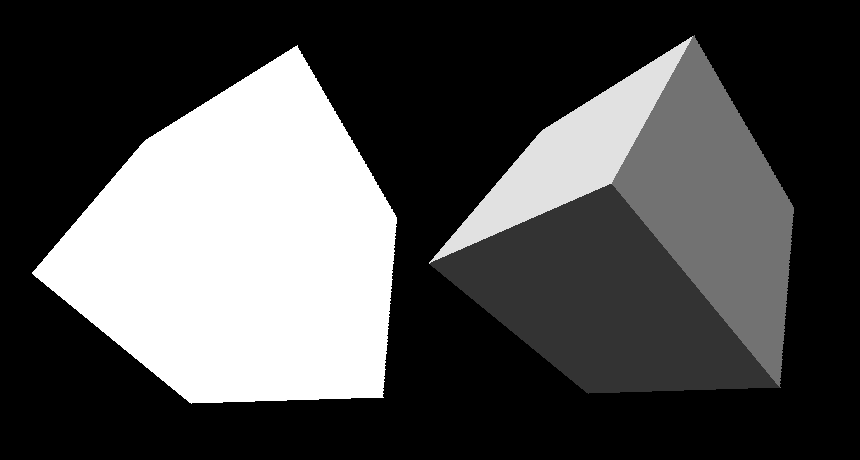
As you can see in the image above, the difference is significant. The cube on the right looks much more like a 3D object. This is surprisingly simple to implement, plus we're going to be able to reuse a lot of logic we've implemented already, and thus, this part will be shorter than the previous ones.
Do you remember how we calculated in the IsBackFace procedure the dot product between the camera and our triangle to determine whether the triangle is facing away from the camera, which is the case when the dot product is 0 or greater?
Today, we're going to use almost the same calculation, but instead of checking if the dot product between the triangle and the camera is 0 or greater, we'll use the dot product between the triangle and the light direction to proportionally adjust the brightness of the color to rasterize a given triangle with.
Before we get to it, let's first implement a simple struct to represent our light with a direction and strength, and also a factory procedure.
Implementing light.odin
Create a new file, call it light.odin, and add the following code.
package main

Light :: struct {
    direction: Vector3,
    strength: f32,
}

MakeLight :: proc(direction: Vector3, strength: f32) -> Light {
    return {
        Vector3Normalize(direction),
        strength
    }
}
As you can see, our light is indeed very simple. We're not going to define a color or position yet. For the super simple flat shading we're implementing today, our light is white and illuminates everything equally from a given direction.
Note that direction should always be normalized. That's why we made a factory procedure where we're using the Vector3Normalize from our vector.odin to make sure it's always the case.
Implementing DrawFlatShaded procedure
Now, let's switch to the draw.odin file and start adding a new procedure, DrawFlatShaded. This will be the entry point for a new render mode, and we'll be calling this procedure from main.odin. The signature will be similar to what DrawUnlit has, but we're also going to pass in our Light and an ambient with the default value of 0.2.
DrawFlatShaded :: proc(
    vertices: []Vector3,
    triangles: []Triangle,
    projMat: Matrix4x4,
    light: Light,
    color: rl.Color,
    zBuffer: ^ZBuffer,
    ambient:f32 = 0.2
) {
The ambient is a float value we're going to use as a lower limit for light intensity to avoid rendering triangles that are pointing away from the light source as completely black.
This is the simplest way to fake global illumination. Although it is very inaccurate, it is inexpensive and, in this case, good enough. In reality, when you have a light source in a room, light bounces off the walls and other objects, so, for example, the bottom of your desk is still illuminated, even though it is not as bright as the top that faces the light source directly. If you have a bright red carpet, the bottom of your desk would even have a slight red tint, even when the light source itself is white, and it is possible to simulate this, even in real time, with a powerful GPU (RTX), but that is far beyond the scope of this series.
In the body of our procedure, we first get our vertices the same way we did in the DrawUnlit and DrawWireframe procedures, but instead of calling IsBackFace, we implement backface culling in place again, because the IsBackFace returns just true or false, but we're going to need that normalized cross product later in this procedure.
for &tri in triangles {
    v1 := vertices[tri[0]]
    v2 := vertices[tri[1]]
    v3 := vertices[tri[2]]

    cross := Vector3CrossProduct(v2 - v1, v3 - v1)
    crossNorm := Vector3Normalize(cross)
    toCamera := Vector3Normalize(v1)

    if Vector3DotProduct(crossNorm, toCamera) >= 0.0 {
        continue
    }
Then we project our vertices to the screen, the same way we did before, and we also use IsFaceOutsideFrustum to skip processing triangles we wouldn't be able to see anyway.
p1 := ProjectToScreen(projMat, v1)
p2 := ProjectToScreen(projMat, v2)
p3 := ProjectToScreen(projMat, v3)

if IsFaceOutsideFrustum(p1, p2, p3) {
    continue
}
And since we already calculated the cross product between two edges that make up our triangle, which is basically a normal of the triangle, for back face culling purposes, we can now use it also to calculate a dot product between this normal and the light direction.
intensity := math.clamp(Vector3DotProduct(crossNorm, light.direction), ambient, 1.0)

shadedColor := rl.Color{
    u8(f32(color.r) * intensity),
    u8(f32(color.g) * intensity),
    u8(f32(color.b) * intensity),
    color.a
}
From Part II of this series, when we talked about backface culling, you know that the dot product is proportional to the angle two vectors form, so we can simply use the dot product as our intensity scaler, clamp it between ambient and 1.0, and multiply each color component with it to get the desired tint of that original color.
Notice we had to cast the color components to be able to multiply them with the intensity 32-bit float value, and then we cast the result back to an unsigned 8-bit integer, which the first three color components, red, green, and blue, are made of. Odin doesn't have implicit casting, which is a good thing, since in C, for example, implicit casts often lead to subtle bugs and unexpected behavior. The fourth component, transparency (alpha), stays unchanged.
And since our DrawFilledTriangle procedure already accepts a color to rasterize the triangle with, we can reuse it, passing the shadedColor instead of the original one, as we do in DrawUnlit.
DrawFilledTriangle(&p1, &p2, &p3, shadedColor, zBuffer)
}
}
That concludes our implementation in draw.odin. All we need to do now is incorporate this new rendering pipeline into our main.odin.
Extending main.odin
Open the main.odin file and create a light pointing downward, with a strength of 1.0. Let's create the light after creating the camera, though the order doesn't matter here. As long as we have these objects, mesh, camera, light, and zBuffer, available when the application enters the main loop, we're good.
light := MakeLight({0.0, 1.0, 0.0}, 1.0)
Then, we need to increment our renderModesCount; we already have 4 of them.
renderModesCount :: 4
And finally, we call the DrawFlatShaded procedure in case renderMode is set to 3, since this is the fourth rendering mode of our main switch. We're passing the same arguments as in the case of DrawUnlit, plus the light, which we pass before color.
switch renderMode {
    case 0: DrawWireframe(mesh.transformedVertices, mesh.triangles, projectionMatrix, rl.GREEN, false)
    case 1: DrawWireframe(mesh.transformedVertices, mesh.triangles, projectionMatrix, rl.GREEN, true)
    case 2: DrawUnlit(mesh.transformedVertices, mesh.triangles, projectionMatrix, rl.WHITE, zBuffer)
    case 3: DrawFlatShaded(mesh.transformedVertices, mesh.triangles, projectionMatrix, light, rl.WHITE, zBuffer)
}
Conclusion
That's all for today. If you now compile and run the program (odin run . -o:speed), you should see a flat shaded white cube, and you should still be able to move it around with the WSADQD keys, rotate it with the IJKLUO keys, scale it using + and -, and cycle through rendering modes with the left and right arrows. If it doesn't work as expected, compare your implementation with the one in the Part 7 directory in this GitHub repository.
Enjoyed this article? Support my work ❤️
All content on this blog, which I've already put hundreds of hours into, is and always will be free.
No ads. No paywalls. No tricks.
I've personally paid for a lot of educational content, but I strongly believe knowledge should be accessible to everyone.
I also pay to keep this blog up and running, and if you like what I do here, if it has helped you, and you would like to support me, you can

Even a small contribution, the price of a coffee, is very much appreciated.
Other Parts of This Series
- Software Renderer in Odin from Scratch, Part I
- Software Renderer in Odin from Scratch, Part II
- Software Renderer in Odin from Scratch, Part III
- Software Renderer in Odin from Scratch, Part IV
- Software Renderer in Odin from Scratch, Part V
- Software Renderer in Odin from Scratch, Part VI
- Software Renderer in Odin from Scratch, Part VII
- Software Renderer in Odin from Scratch, Part VIII
- Software Renderer in Odin from Scratch, Part IX
- Software Renderer in Odin from Scratch, Part X
- Software Renderer in Odin from Scratch, Part XI
- Software Renderer in Odin from Scratch, Part XII
- Software Renderer in Odin from Scratch, Part XIII
- Software Renderer in Odin from Scratch, Part XIV


