Software Renderer in Odin from Scratch, Part VI
13th September 2025 • 20 min read
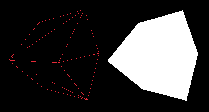
In the previous part, we finally drew something on the screen, a wireframe cube, and we even implemented a basic optimization technique, the backface culling. Today, we're going to build on that by implementing the third render mode, where, instead of connecting points with lines, as we did to draw the wireframe, we’ll fill triangles with pixels to make our cube appear solid.
However, since all pixels will have the same color, there will be no shading, and our cube will look flat. We'll address this in the next part, when we'll implement flat shading, where the intensity of a color for the entire triangle will be affected by the angle between the triangle and the light direction.
In this part, we're also going to implement a depth buffer, also known as a z-buffer. This helps us to prevent overdrawing pixels that are closer to the camera from those that are supposed to be behind them.
But first, let's briefly discuss how we can fill a triangle with pixels using the Flat-Top Flat-Bottom (FTFB) rasterization technique.
Flat-Top Flat-Bottom
The FTFB rasterization technique for filling triangles is named after the idea of splitting any arbitrary triangle into two, one with a flat top and the other with a flat bottom. It is a relatively simple and efficient method.
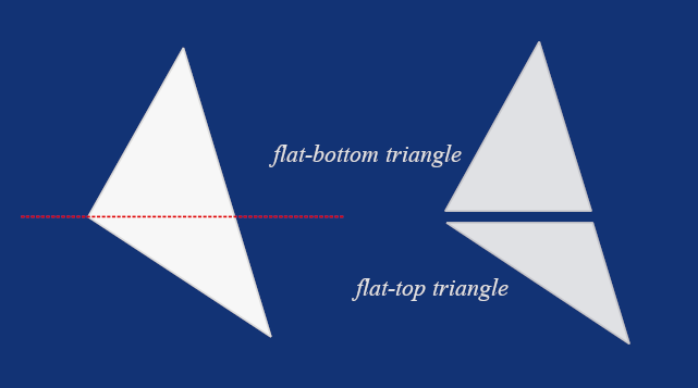
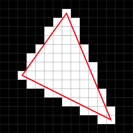
To split the original triangle, we first need to sort its points by their Y-coordinate. Then, we can process each of the resulting triangles like this: for every horizontal line (a.k.a. scanline), we determine the left and right edge positions on the triangle and draw pixels between them from left to right. Then we repeat the process for all scanlines, from top to bottom, until the entire triangle is filled with pixels, or, in other words, until the entire triangle is rasterized.
This very simplified, high-level understanding of the FTFB technique should be enough for now. Once we start implementing the algorithm in Odin, I'll explain it line by line.
Depth Buffering
Another concept we're going to cover today is the depth buffering, also known as the z-buffering. The idea is based on creating an array with one entry per screen pixel, which means its size is calculated as screen width times screen height.
Initially, each entry is set to a very large value (representing "infinite" depth) and each frame, when we're about to draw a point, we check whether its z-coordinate is smaller than the value currently stored as the corresponding entry of the depth buffer and only in that case, we draw the point and update that entry with the new z-coordinate.
This ensures points closer to the camera overwrite points farther away, and vice versa, preventing hidden geometry from being drawn over visible ones. We also mustn't forget to clear our depth buffer at the beginning of each frame by setting all values back to the initial large value. We're going to implement a procedure for that.
Again, this should be enough as an introduction to the concept. We'll get to implementation and its in-depth (pun intended) explanation soon. But first, let's implement sort.odin with a procedure we’re going to need for the FTFB algorithm.
Implementing sort.odin
Our sorting procedure will be quite simple, and we're going to use two neat Odin features. Create a new file, name it sort.odin, and type in the following code:
package main

Sort :: proc {
    SortPoints
}

SortPoints :: proc(p1, p2, p3: ^Vector3) {
    if p1.y > p2.y {
        p1.x, p2.x = p2.x, p1.x
        p1.y, p2.y = p2.y, p1.y
        p1.z, p2.z = p2.z, p1.z
    }
    if p2.y > p3.y {
        p2.x, p3.x = p3.x, p2.x
        p2.y, p3.y = p3.y, p2.y
        p2.z, p3.z = p3.z, p2.z
    }
    if p1.y > p2.y {
        p1.x, p2.x = p2.x, p1.x
        p1.y, p2.y = p2.y, p1.y
        p1.z, p2.z = p2.z, p1.z
    }
}
As you can see, we first check whether the Y-coordinate of the first point is greater than that of the second, and if so, we swap them. Next, we perform the same check for the second and third points, and finally, we repeat the check between the first and second points again, because the second point may have changed after the second comparison. This guarantees that the points are sorted in ascending order by their Y-coordinates.
However, notice how we are swapping values in Odin without using a temporary variable, just by writing p1.x, p2.x = p2.x, p1.x, pretty neat, right? You might also be wondering, what are these lines for:
Sort :: proc {
    SortPoints
}
This is Odin's explicit procedure overloading. It might look unnecessary, since we only have one procedure, but later we'll add more procedures for sorting not just projected points, but also vertices, normals, and UVs.
With procedure overloading, in draw.odin, we'll be able to call Sort with different parameters. In fact, this indirection is indeed unnecessary, but since this is a tutorial code, I saw this as a good opportunity to showcase an Odin language feature you might not know about.
Implementing zbuffer.odin
Our sort.odin is complete, for now. It's time to introduce a depth buffer. Create a new file called zbuffer.odin. This one will be even shorter; all we need to do is define a type alias and add a procedure for clearing our depth buffer.
I decided to use ZBuffer in the code because, in our implementation, the Z-axis represents depth. In the text, however, I'll refer to it, using a more generic term, as a depth buffer.
package main

ZBuffer :: [SCREEN_WIDTH * SCREEN_HEIGHT]f32

ClearZBuffer :: proc(zBuffer: ^ZBuffer) {
    for i in 0..<len(zBuffer) {
        zBuffer[i] = 999_999;
    }
}
We already have the SCREEN_WIDTH and SCREEN_HEIGHT defined in constants.odin, and the depth buffer itself is simply an array of 32-bit floats with a size of screen width times screen height. When clearing the buffer, notice that in Odin, we can split large numeric literals by inserting underscores. That's another neat little feature Odin provides for improving the readability of large numbers.
Extending vectors.odin
To avoid visual artifacts, we need to floor the x and y coordinates of projected points at the beginning of our rasterization algorithm, right after sorting. For this, we're going to add a small utility function to our vectors.odin that uses math.floor from Odin's core:math package.
FloorXY :: proc (v: ^Vector3) {
    v.x = math.floor(v.x)
    v.y = math.floor(v.y)
}
Implementing FTFB Algorithm
Now we have all the utilities we need to implement another rendering pipeline in the draw.odin. Let's start by adding a new procedure, which we'll later call in main.odin from the switch block where DrawWireframe is currently called. We're going to name this new procedure DrawUnlit.
DrawUnlit :: proc(
    vertices: []Vector3,
    triangles: []Triangle,
    projMat: Matrix4x4,
    color: rl.Color,
    zBuffer: ^ZBuffer
) {
    for &tri in triangles {
        v1 := vertices[tri[0]]
        v2 := vertices[tri[1]]
        v3 := vertices[tri[2]]

        if IsBackFace(v1, v2, v3) {
            continue
        }

        p1 := ProjectToScreen(projMat, v1)
        p2 := ProjectToScreen(projMat, v2)
        p3 := ProjectToScreen(projMat, v3)

        if IsFaceOutsideFrustum(p1, p2, p3) {
            continue
        }

        DrawFilledTriangle(&p1, &p2, &p3, color, zBuffer)
    }
}
If you compare DrawUnlit with DrawWireframe, and I encourage you to do so, you'll notice it's almost identical. Once again, we retrieve the vertices of each triangle, perform a backface culling check, then we project the vertices to screen space, and check if the projected points lie inside the frustum.
The key difference is in how we handle the projected points that pass our checks. Instead of drawing lines between them with DrawLine, we rasterize the triangle these points make via DrawFilledTriangle, a procedure we're now going to implement. Also notice how we pass through this method our depth buffer.
Let's now implement the DrawFilledTriangle procedure, and de facto the FTFB rasterization algorithm, step by step, starting with its signature:
DrawFilledTriangle :: proc(
    p1, p2, p3: ^Vector3,
    color: rl.Color,
    zBuffer: ^ZBuffer
) {
As you can see, we need nothing more than projected points, a color to draw the triangle with, and a reference to our depth buffer.
At the beginning of the procedure, we sort the points and then floor their X and Y coordinates, using our utility procedures:
Sort(p1, p2, p3)

FloorXY(p1)
FloorXY(p2)
FloorXY(p3)
With the points sorted, we can now proceed with drawing both the flat-bottom and flat-top parts of the original triangle defined by p1, p2, and p3.
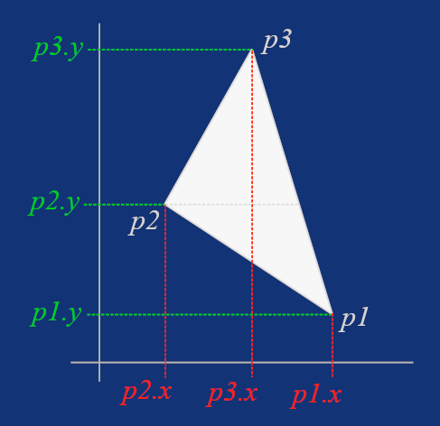
However, if the triangle is already flat-bottom or flat-top, we want to skip the other part. That's why we wrap the rasterization of the flat-bottom triangle with a p2.y != p1.y check, and the flat-top with a p3.y != p1.y check.
Let's start with drawing the flat-bottom triangle, step by step. After the check mentioned above, we need to calculate the inverse slopes (dx/dy) between the second and first point, and between the third and first point.
// Draw a flat-bottom triangle
if p2.y != p1.y {
    invSlope1 := (p2.x - p1.x) / (p2.y - p1.y)
    invSlope2 := (p3.x - p1.x) / (p3.y - p1.y)
Then, for each scanline, that is, for each Y-coordinate between the first and second point, we use the inverse slope to determine the left and right boundaries of the triangle on that scanline, which we name xStart and xEnd.
However, the flat-bottom triangle may be oriented such that after this calculation, xStart is actually on the right and xEnd on the left. In that case, xStart is greater than xEnd and all we need to do is simply swap them. Notice again that in Odin, we don't need a temporary variable, as we've already seen in our sorting procedure.
ㅤㅤfor y := p1.y; y <= p2.y; y += 1 {
        xStart := p1.x + (y - p1.y) * invSlope1
        xEnd := p1.x + (y - p1.y) * invSlope2

        if xStart > xEnd {
                xStart, xEnd = xEnd, xStart
        }
Now that we have the boundaries for the scanline, we simply draw pixels from left to right, from xStart to xEnd, using the DrawPixels procedure, which we have yet to implement.
ㅤㅤfor x := xStart; x <= xEnd; x += 1 {
        DrawPixel(x, y, p1, p2, p3, color, zBuffer)
    }
And that's all for the flat-bottom triangle. To rasterize a flat-top triangle, the process is fundamentally the same, but instead of working with p2 and p1, we now work with p3 and p1.
// Draw flat-top triangle
if p3.y != p1.y {
        invSlope1 := (p3.x - p2.x) / (p3.y - p2.y)
        invSlope2 := (p3.x - p1.x) / (p3.y - p1.y)

        for y := p2.y; y <= p3.y; y += 1 {
            xStart := p2.x + (y - p2.y) * invSlope1
            xEnd := p1.x + (y - p1.y) * invSlope2

            if xStart > xEnd {
                xStart, xEnd = xEnd, xStart
            }

            for x := xStart; x <= xEnd; x += 1 {
                DrawPixel(x, y, p1, p2, p3, color, zBuffer)
            }
        }
    }
}
That concludes our DrawFilledTriangle procedure, but there's still work to do. Apart from implementing DrawPixel, we also need yet another utility procedure, this time to calculate barycentric weights.
Barycentric Weights
Since we are now, with depth buffering, working in a per-pixel domain, the positions of the three vertices that define our triangle are not enough. We also need to determine the positions of points inside the triangle, and calculating barycentric weights (or barycentric coordinates) is the concept that fits this need perfectly.
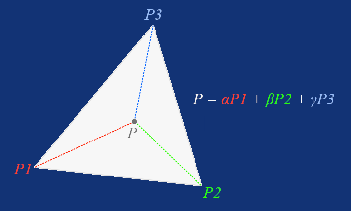
Given a triangle with vertices P1, P2, and P3, we can express any point inside (or even outside the triangle, to be technically correct) as:
Where α, β, and γ are barycentric weights that tell us how much each vertex contributes to the position of our point.
Intuitively, if a point lies at the same position as P1, then α = 1, β = 0, and γ = 0. If the point is halfway on the line between P1 and P2, then α = β = 0.5 and γ = 0, and if the point is exactly at the centre of a triangle, then α = β = γ = 1/3.
That means, the sum of α, β, and γ must always be 1, and if any of these barycentric weights is negative, then the point lies outside the triangle. However, in our use-case, a point will always be inside a triangle.
But how do we actually calculate these weights? Let's implement a procedure that accepts the vertices of a triangle and a point, and returns the barycentric weights for that point packed in a Vector3, step by step, starting with its signature:
BarycentricWeights :: proc(a, b, c, p: Vector2) -> Vector3 {
Inside the procedure, we first calculate the vectors between the triangle vertices, as well as the vectors from the point p to the vertices. This should be familiar by now: a simple vector subtraction can be used to find the direction from one point to another.
ac := c - a
ab := b - a
ap := p - a
pc := c - p
pb := b - p
Next, we use ac and ab to calculate the area, which is actually twice the size of the triangle. This is fine because we only use it to calculate ratios for the barycentric weights, so the factor of two cancels out in the division.
area := (ac.x * ab.y - ac.y * ab.x)
Once we have the overall area, we can calculate alpha simply by calculating twice the area of the triangle formed by the vertices p, b, and c, and dividing it by the overall area we calculated using ac and ab vectors.
alpha := (pc.x * pb.y - pc.y * pb.x) / area
And similarly beta, using the second sub-triangle formed by p, a, and c:
beta := (ac.x * ap.y - ac.y * ap.x) / area
Since the sum of alpha, beta, and gamma must always be 1, we can calculate the third weight by simply subtracting the first two from 1.0. Then we return all three weights packed in a Vector3.
gamma := 1.0 - alpha - beta

return Vector3{alpha, beta, gamma}
Drawing Pixels with Depth Buffer
Now that we have our BarycentricWeights utility procedure, which we'll later use for UV mapping and Phong shading as well, we can start implementing the DrawPixel procedure in the draw.odin file, using our depth buffer to prevent pixel overdrawing.
But before that, let's quickly implement a simple optimization procedure to check whether the x and y screen coordinates we wish to draw a pixel on are indeed inside the window. In other words, it determines whether these coordinate lies within the bounds of 0 and SCREEN_WIDTH on the X axis and 0 and SCREEN_HEIGHT on the Y axis.
IsPointOutsideViewport :: proc(x, y: i32) -> bool {
    return x < 0 || x >= SCREEN_WIDTH || y < 0 || y >= SCREEN_HEIGHT
}
Now we can finally proceed with implementing DrawPixel. Let’s start with its signature.
DrawPixel :: proc(
    x, y: f32,
    p1, p2, p3: ^Vector3,
    color: rl.Color,
    zBuffer: ^ZBuffer
) {
As you can see, we pass in x and y to draw a pixel of a given color, along with the points that define the triangle we are currently rasterizing and a reference to our depth buffer.
Next, we cast x and y to integers, introducing ix and iy, and use them to check whether the point is outside the window by calling the IsPointOutsideViewport procedure we just implemented. If so, we return early. There's no reason to draw pixels that cannot be seen.
ix := i32(x)
iy := i32(y)
if IsPointOutsideViewport(ix, iy) {
    return
}
Now we create a point p of type Vector2 from the original x and y and we pass it, along with the points that define our triangle, into the BarycentricWeights procedure. Then we deconstruct the returned weights into alpha, beta, and gamma. This is optional, but for a tutorial code, I find it a little bit clearer. If you disagree, feel free to use x, y, and z components of weights directly.
p       := Vector2{x, y}
weights := BarycentricWeights(p1.xy, p2.xy, p3.xy, p)
alpha   := weights.x
beta    := weights.y
gamma   := weights.z
Also notice how we pass Vector2 values into BarycentricWeights even though p1, p2, and p3 are Vector3. Notice that Vector2 and Vector3 are actually just our aliases for [2]f32 and [3]f32 arrays. Here comes another neat feature of Odin, it not only allows us to access the first, second, and third elements of f32[3] with .x, .y, and .z, but also lets us discard the third component and create a new f32[2] from f32[3] using a nicely concise .xy (or .rg) syntax. There is more to it that I'm not covering here, but I highly recommend you read the Array Programming section in the Odin documentation, if you haven't done so already.
Having our barycentric weights, we can now use them to calculate depth by dividing 1.0 by the sum of these weights multiplied by the corresponding z components of p1, p2, and p3.
denom  := alpha*p1.z + beta*p2.z + gamma*p3.z
depth  := 1.0 / denom
Remember how we calculated inverse W as 1.0 divided by the fourth component (W) of a point transformed to clip space in the ProjectToScreen procedure. Depth buffering is the reason we did this and why we kept the projected point as a Vector3, so we can store this invW as the z component of the projected points that we now use to calculate the denominator for per-pixel depth calculation.
Finally, we check if the value in our depth buffer for the corresponding screen coordinates is smaller than the calculated depth to only draw the pixel with raylib's DrawPixel if this is the case. And when drawing the pixel, we mustn't forget to update the depth value in the depth buffer.
zIndex := SCREEN_WIDTH*iy + ix
if (depth < zBuffer[zIndex]) {
rl.DrawPixel(ix, iy, color)
zBuffer[zIndex] = depth
}
}
That concludes our DrawPixel procedure. The last thing we need to do now is extend main.odin to use the new rendering mode.
Extending main.odin
We don't need to do much in main.odin, all the heavy lifting we've done already. Now we just need to create our depth buffer, let's do that after we create our camera:
zBuffer := new(ZBuffer)
We don't need a factory procedure for zBuffer, since it's fundamentally just an array. We also need to increment renderModesCount from 2 to 3.
renderModesCount :: 3
And finally, we need to clear the depth buffer every frame before drawing, and add a new case to our main switch to call DrawUnlit when renderMode is set to 2. This updated part of the code in main.odin should look like this:
ClearZBuffer(zBuffer)

switch renderMode {
    case 0: DrawWireframe(mesh.transformedVertices, mesh.triangles, projectionMatrix, rl.GREEN, false)
    case 1: DrawWireframe(mesh.transformedVertices, mesh.triangles, projectionMatrix, rl.GREEN, true)
    case 2: DrawUnlit(mesh.transformedVertices, mesh.triangles, projectionMatrix, rl.WHITE, zBuffer)
}
Conclusion
And that's it for today. If you now compile and run the program (odin run . -o:speed), you should see an unlit white cube. You should still be able to move it around with the WSADQD keys, rotate it with the IJKLUO keys, and cycle through rendering modes with the left and right arrows. If it doesn't work as expected, compare your implementation with the one in the Part 6 directory in this GitHub repository.
Enjoyed this article? Support my work ❤️
All content on this blog, which I've already put hundreds of hours into, is and always will be free.
No ads. No paywalls. No tricks.
I've personally paid for a lot of educational content, but I strongly believe knowledge should be accessible to everyone.
I also pay to keep this blog up and running, and if you like what I do here, if it has helped you, and you would like to support me, you can

Even a small contribution, the price of a coffee, is very much appreciated.
Other Parts of This Series
- Software Renderer in Odin from Scratch, Part I
- Software Renderer in Odin from Scratch, Part II
- Software Renderer in Odin from Scratch, Part III
- Software Renderer in Odin from Scratch, Part IV
- Software Renderer in Odin from Scratch, Part V
- Software Renderer in Odin from Scratch, Part VI
- Software Renderer in Odin from Scratch, Part VII
- Software Renderer in Odin from Scratch, Part VIII
- Software Renderer in Odin from Scratch, Part IX
- Software Renderer in Odin from Scratch, Part X
- Software Renderer in Odin from Scratch, Part XI
- Software Renderer in Odin from Scratch, Part XII
- Software Renderer in Odin from Scratch, Part XIII
- Software Renderer in Odin from Scratch, Part XIV


